In Military, aerospace, and high-quality industrial and communications systems, the high-speed Ethernet connector and cable combination carry broadband signals in hostile environments between modems, routers, computers, and other wired internet-capable devices. In these hostile environments, high-speed, quality Ethernet connectors must be capable of maintaining transmission integrity and enduring shock & vibration environments. This article explores the required Ethernet 10GBase-T electrical and shock & vibration tests and then presents a standard RJ45 solution for this environment and possible future alternatives.
What is Category 6a Cabling?
Category 6a or Cat 6a is the latest iteration of Gigabit Ethernet cabling. The Cat 6a increases the data transmission bandwidth from 250 to 500 Megahertz (MHz), decreasing crosstalk interference chances and providing superior reliability and transmission speeds through greater lengths of cable. Cat 6a 10-Gigabit Ethernet is an augmented standard to Category 6 (Cat 6) and is backwards compatible with the older Category 5/5e cable standards.
| Cable Type | Bandwidth | Max Speed at 100m |
| Cat 5 | 100MHz | 1Gbps |
| Cat 5e | 100MHz | 2.5Gbps |
| Cat 6 | 250MHz | 5Gbps |
| Cat 6a | 500MHz | 10Gbps |
Table 1: Comparison of Cat 5/5e and Cat 6/6a cable bandwidths and maximum data rates for cable lengths up to 100m
Ethernet Electrical Test Qualification
The transmission rate of 10G Ethernet is not one bit per cycle or 10 Gigabits-per-second (Gbps). Sending one bit per cycle at those speeds creates signal integrity issues, requires expensive high-speed connectors, and limits the length of the transmission path. To achieve high bit rates while avoiding these issues, 10G Ethernet employs modulation techniques that transmit more than one bit of information per cycle (baud) at lower frequencies. Baud is the symbol rate at which a communications medium operates.
A baud symbol can contain more than one bit. Multi-bit symbols allow higher throughputs at lower frequencies. 10G Ethernet employs 16 level pulse-amplitude modulation (PAM16) double square (DSQ) coded resulting in 3 bits per symbol. Symbols are transmitted at 833Mbaud over four twisted wire pairs resulting in a total bit rate of 10 Gbps.
Equation 1 shows the bit rate translation.
Bit rate = 833.3 Mbaud * 3 bits/baud * 4 (pairs) = 10 Gbps.
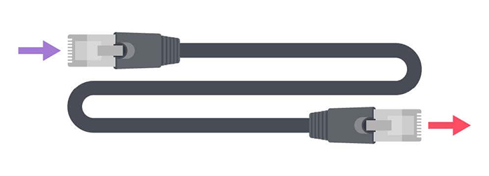
The Ethernet electrical test environment is through input and output connectors and the connecting cables (See Figure 1).
Figure 1: Cat 6a unshielded twisted pair (UTP) Ethernet cable with RJ45 end connectors
The 10GBase-T Cable Compliance Testing configurations evaluate the performance to the cable’s Category 6a cable compliance standard (ANSI/TIA/EIA-568-B.2). Test results determine if existing shielded (STP) and unshielded (UTP) twisted pair cable and connector configurations meet the electrical standards.
Electrical Ethernet Testing
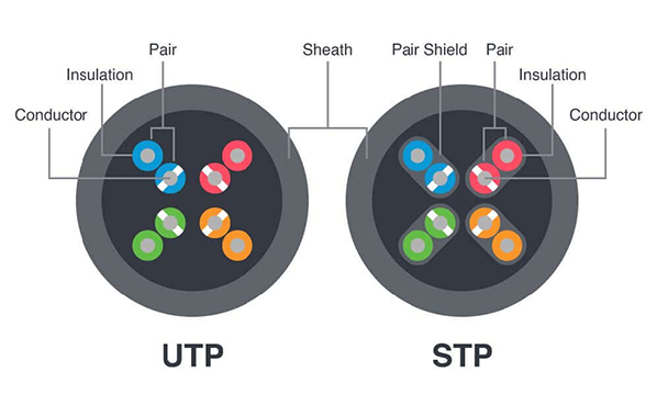
The two cabling versions are STP (shielded twisted pair) and UTP (unshielded twisted pair), where the twisted pairs in an STP cable are each shielded (Figure 2).
Figure 2: Cross section of shielded (STP) and unshielded (UTP) cable
The two categories of the twelve test parameters are crosstalk and signal. The crosstalk parameters test for coupling between the twisted wire pairs across the cable and signal parameters test the electrical integrity of each of the cable wires. If the tested parameters do not meet 10GBase–T Cat 6a requirements, your system will compromise the network. These tests and their abbreviations are listed in table 2.
| Category | Test | Abbreviation |
| Crosstalk | Near end crosstalk | NEXT |
| Far end crosstalk | FEXT | |
| Power sum near end crosstalk | PS NEXT | |
| Attenuation to crosstalk ratio - near end | ACR-N | |
| Attenuation to crosstalk ratio - far end | ACR-F | |
| Power sum attenuation to crosstalk ratio - near end | PS ACR-N | |
| Power sum attenuation to crosstalk ratio - far end | PS ACR-F | |
| Signal | Return loss | RL |
| Insertion loss | IL | |
| Propagation delay | PD | |
| Propagation delay skew | PDS |
Table 2: List of crosstalk and signal tests and abbreviations
Standard testers exist for evaluating compliance with Ethernet 10GBase-T Cable requirements, including Fluke Networks DSX-500 and DSX-8000 cable analyzers.
Crosstalk Tests
In a transmission system, crosstalk is when one circuit or channels’ transmitted signal creates an undesired effect in another circuit or channel. Crosstalk is usually a result of undesired capacitive, inductive, or conductive coupling from one circuit or channel to another.
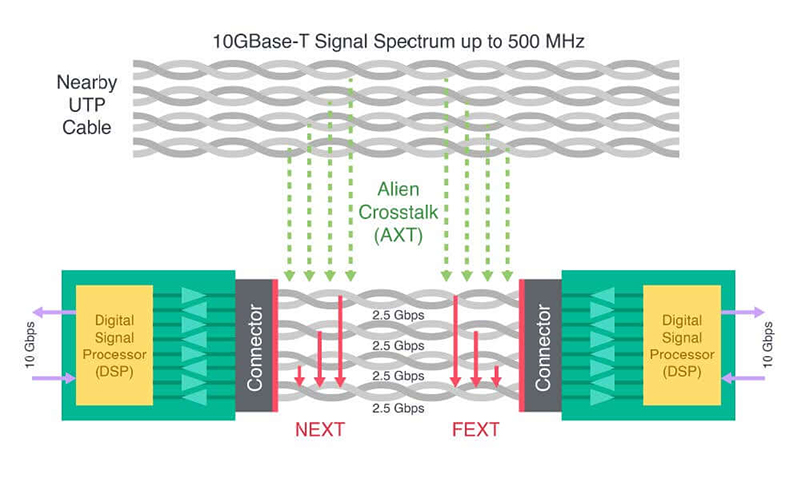
The most critical 10GBase-T Ethernet Cable/Connector crosstalk test parameter is NEXT or near-end crosstalk. NEXT is one of the most crucial cable measurements because it measures the coupled signal interference from the connector’s one wire pair to an adjacent pair on the cable end nearest (near-end) to the test device (Figure 3).
Ethernet's twisted-pair cables have four pairs of wires. These wires twist around each other to reduce crosstalk and outside interference. Current LANs commonly use this type of cabling.
Figure 3. The 10GBase-T internet system with an illustration of the connector’s near-end (NEXT), far-end (FEXT), and alien crosstalk (AXT) interference sources
The NEXT test measures the signal strength difference between a disturbing pair and a victim pair. A more significant number (less crosstalk) is more desirable than a smaller number (more crosstalk). Because NEXT varies significantly with frequency, it is essential to measure it across the applicable range of frequencies. Cat 6a is characterized up to 500 MHz.
FEXT, PS NEXT, ACRN, ACRF, PSACRN, and PSACRF are the secondary crosstalk parameters. The measurement of far-end crosstalk (FEXT) is also within a channel. It is similar to NEXT, but the measurement point is at the channel’s far-end. However, FEXT is not the complete story since distance attenuates signals. A more significant result removes the attenuation (insertion loss) from the FEXT result to create the attenuation to crosstalk ratio parameter (ACRF).
Finally, alien crosstalk (AXT) becomes a concern in the Ethernet Category 6A 10GBASE-T applications. Once applications move to the higher frequencies, which is valid with the Ethernet Category 6A 10GBASE-T applications, there is a worry about cable-to-cable crosstalk.
Alien crosstalk is the term for coupling noise from one cable to another. This crosstalk error occurs when a bundle of many cables surrounds or disturbs a single cable. The cables that surround an individual cable in a bundle are the Disturbers. The cables that suffer from Disturber noise are the Victim cable.
This disturbance becomes more critical as faster applications increase the bandwidth requirement of cables as Disturbers can impact the Victim's ability to transmit data. The user might think shielded cables, inner or outer cable shields, alleviate the alien crosstalk. A poor shield termination in a shielded system can introduce alien crosstalk.
Signal Tests
The four signal test parameters are described in table 3:
| Test | Name | Description |
| RL | Return loss | a measure, expressed in decibel (dB), of all impedance mismatch reflections at all locations along with the link. |
| IL | Insertion loss | the amount of energy loss, in decibels (dB), that is lost as the signal arrives at the receiving end quantifies the cabling link resistance effect. |
| PD | Propagation delay | the time required for a signal to propagate from one end of the circuit to the other. |
| PDS | Propagation delay skew | the difference between the propagation delay on the fastest and slowest pairs in an unshielded twisted pair (UTP) cable |
Table 3: Signal tests and descriptions
The most critical 10GBase-T Cable signal parameters are return loss (RL) and insertion loss (IL) when meeting Military and high-quality industrial applications. Return loss is a vital test measurement of local area networks (LAN), especially those migrating to higher speed protocols.
Ethernet Shock and Vibration Qualification
Military and industrial tools and equipment must perform reliably in some of the harshest environments, from the ocean’s depths to the hottest of deserts. In addition to inhospitable natural conditions and equipment-intensive production floors, Military and industrial environments must endure gunfire shock, transportation vibration, and explosive and acidic atmospheres. In these environments, the complexion of shock and vibration seem indeterminate.
Reduce SWaP for Military & Aerospace Applications
Learn HowThe widely used MIL-STD-810 specification includes a comprehensive collection of thirty environmental tests, related to vibration, shock, acoustic noise, temperature, humidity, solar radiation, sand, and dust.
Vibration describes a mechanical system’s oscillation. The vibration specification measure is frequency, cycles per second, and amplitude or magnitude. In practice, a vibration often does not have a regular pattern. The vibration signal may combine several sinusoidal quantities, each having different frequencies and amplitudes.
The high-level categories of vibration are either “free” or “forced.” In free vibration, the structure changes per the initial disturbance, and there is no energy added to the system. A forced vibration continues to oscillate under “steady-state” conditions.
The definition of shock is loosely an aspect of vibration. The shock energy can be a nonperiodic pulse, step, or transient vibration, and shock suggests suddenness and severity. The essential characteristic is that after the shock, the system’s motion includes the frequency of the shock excitation and the system’s natural frequency. With a brief excitation, the continuing motion of the system is a free vibration mass at its natural frequency.
Although the RJ45 connector can comply with all 10GBase-T Cable electrical compliance testing, the MIL-STD-810 shock and vibration test compliance go beyond the capability of this connector.
Ethernet Connector Technology
The Military and Industrial Ethernet systems weave the communication channels together. The integrity of the cables and connectors establishes the usability of the 10GBase-T system.
The critical links in these systems are the connectors and cables. The standard Ethernet connector is the RJ45 (Figure 4).
Figure 4: RJ45 connectors cannot sustain shock and vibration environments, but the Micro-D connector uses durable twist-pin contacts to overcome stiff MIL-STD-810 shock and vibration test compliance.
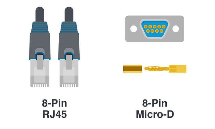
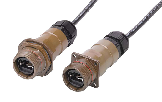
The low-cost, small RJ45 connector successfully meets the electrical requirements for a 10GBase-T Ethernet connection, but it does not meet Military MIL-STD-810 shock and vibration test compliance. The 38999 connectors effectively tackle the shock and vibration problem by encapsulating the RJ45 connector in a rugged shell (Figure 5). However, because this solution to shock & vibe is large and expensive, smaller more cost-effective solutions are being studied. Connectors, such as Cinch’s micro-D, which can already meet shock & vibration requirements, are being evaluated to see if they can be designed to meet 10GBase-T requirements over Cat 6 cable (Figure 4).
Figure 5: To address the MIL-STD-810 shock and vibration requirements, the 38999 encapsulates the RJ45 connector.
Harsh Environment Considerations for 10GBase-T
Military and high-quality industrial and communications systems are using high-speed Ethernet 10GBase-T connectors and cable combinations to carry broadband signals in hostile environments. The high-speed Ethernet connectors must be capable of maintaining transmission integrity and enduring shock & vibration environments per the MIL-STD-810 standard. The electrical compliance challenge is easy to address with existing technologies. However, the shock and vibration compliance testing requires additional attention from the designer as he works to reduce connector size and cost. Today, the viable alternative with the RJ45 connector is housed in the large-sized, higher-cost 38999 connectors.
View Cinch's Full Line of Products for the Harshest Environments
Learn More